What are you looking for?

The industrial chimney construction process starts long before steel reaches the site. It moves through design-basis confirmation, structural and thermal engineering, shop detailing, material control, fabrication, inspection, transport planning, foundation verification, erection and final acceptance. Each stage must use the same approved process data and interface dimensions. A late change in gas temperature, duct load or chimney height can affect the liner, shell, foundation and lifting plan. Rainbow supplies engineered industrial steel chimney systems for power, boiler, chemical, waste-to-energy and other plant applications, with design, manufacturing and EPC support coordinated around project-specific requirements.
| Stage | Main work | Key output or hold point |
|---|---|---|
| 1. Design basis | Confirm process, site, code and interface data | Approved design basis and responsibility matrix |
| 2. Engineering | Complete flow, thermal, structural, vibration, liner and foundation design | Approved calculations and general arrangement |
| 3. Shop detailing | Split the chimney into transport and erection sections | Fabrication drawings and bill of materials |
| 4. Procurement | Control plates, liners, bolts, welding consumables and coatings | Traceable materials and approved suppliers |
| 5. Fabrication | Cut, roll, weld, fit and preassemble components | Released chimney sections |
| 6. Inspection | Check dimensions, welds, coatings and documentation | Inspection release and manufacturing record book |
| 7. Logistics | Protect, support and deliver large sections | Approved packing, route and lifting plan |
| 8. Installation | Verify foundation, lift sections, align and connect systems | Mechanical completion |
| 9. Handover | Inspect, test and compile final records | Accepted as-built package |
The stages overlap. Transport limits affect shell segmentation, and the erection method affects lifting details. Good project control closes these interfaces before fabrication begins.
The design basis turns the owner’s process and site information into one controlled engineering input. It should state what the chimney must carry, what gas it must handle, which rules govern the work and who is responsible for each interface.
Process data normally include gas flow, normal and upset temperature, pressure, moisture, dust, oxygen and corrosive components. The operating profile also matters. Continuous hot service, frequent shutdowns and low-load operation create different condensation and thermal-cycle risks.
Site data include wind, seismic demand, ambient temperature, terrain, altitude, icing if relevant, corrosive atmosphere and geotechnical conditions. The project team must also confirm the required release height, gas-path diameter, duct elevation, duct reactions, platform levels, access system, monitoring ports, aviation warning requirements and lightning protection.
The governing standard and edition must be explicit. Steel-stack projects may use ASME STS-1, EN 13084, CICIND, a national chimney code or a contract-defined combination. Linked requirements can cover structural steel, welding, coatings, bolts, concrete, cranes, fall protection and local environmental approval. A written code hierarchy prevents conflicting assumptions later.

Engineering converts the design basis into a chimney that can be fabricated, transported, erected and maintained. This phase should coordinate process performance with structural behavior instead of treating them as separate packages.
The gas-path diameter must support the required flow and acceptable pressure loss. The designer checks gas velocity, draft, heat loss and outlet conditions. Insulation and liner design should limit heat transfer, control condensation risk and allow movement between hot and cold components.
Expansion joints, sliding supports and liner guides need enough movement capacity for normal and upset conditions. A rigid connection in the wrong place can transfer large thermal forces into the shell, duct or equipment nozzle.
The structural model includes dead load, wind, seismic effects, thermal actions, platforms, ladders, ducts, liners and other appurtenances. Tall or slender stacks may need dynamic wind and vortex-shedding checks. Local analysis is important around the breeching opening, access doors, base transition, anchor bolts and major platform brackets.
Foundation design uses shell reactions together with the geotechnical report. The engineer checks bearing, sliding, overturning, settlement and reinforcement. Anchor-bolt geometry must match the base plate and installation template. The self-supporting steel chimney arrangement also needs coordinated separation of the supporting shell, inner flue, insulation and air space.
The chimney is divided into shop and field sections based on plate size, rolling capacity, coating access, transport envelope, crane capacity and site space. Field joints should be accessible and should avoid unnecessary work at height. Lifting lugs, temporary stiffeners, rigging clearances and section centers of gravity must be designed, not improvised on site.
Before drawings are released, the project team should complete a constructability review. It should confirm the erection sequence, temporary stability, crane position, ground bearing capacity, exclusion zones and installation of ladders, platforms, liners and accessories.
Approved shop drawings must carry the engineering intent into the factory. They show plate development, shell courses, longitudinal and circumferential welds, stiffeners, flanges, openings, platforms, ladders, liner supports, lifting points and field connections.
The bill of materials links each component to its grade, thickness and specification. Material certificates should be checked against the purchase order before production. Traceability should remain clear after plates are cut into smaller parts.
Material selection depends on duty. Carbon steel may form the supporting shell, while the gas-contact system can use stainless steel, duplex stainless steel, titanium-clad steel, FRP or another corrosion-resistant solution. Welding consumables, bolts, gaskets, insulation and coatings must match the approved specifications and service temperature.
A project inspection and test plan should identify witness points, hold points, acceptance criteria and required records. The owner, EPC contractor, manufacturer and third-party inspector need to agree on this plan before production starts.
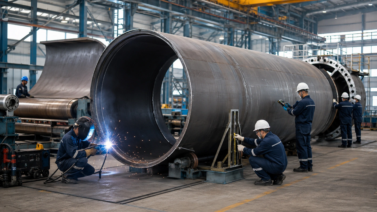
Factory fabrication controls geometry and joint quality before the sections reach the site. Typical work includes plate preparation, rolling, fit-up, welding, dimensional inspection, attachment installation, preassembly and surface protection.
Plates are cut, edge-prepared and rolled into shell courses. Fit-up controls root gap, alignment, roundness and joint offset before welding. Courses can then be joined into larger transport sections.
Welding must follow approved procedures with qualified personnel. The American Welding Society states that AWS D1.1/D1.1M:2025 covers design, fabrication, qualification and inspection for welded carbon and low-alloy structural steel. The project must still use the welding code named in its contract and confirm whether special materials require other procedures. See the AWS D1.1 release information.
Inspection can include visual testing, dimensional checks and the nondestructive examination required by the project. Inspectors also check openings, flanges, base-ring geometry, lifting lugs and platform connections. Trial assembly can confirm that major interfaces fit before shipping.
Surface preparation and coating follow only after required weld inspections are complete. Areas needed for field welding may receive temporary protection instead of the final system. Stainless or clad gas-contact surfaces need suitable handling to avoid contamination and damage.
A complete manufacturing record normally contains material certificates, welding procedure and qualification records, welder records, inspection reports, nondestructive examination results, dimensional reports, coating records and approved concessions.
Large chimney sections need supports that prevent ovalization and coating damage. The logistics plan should check section length, diameter, weight, lifting points, route limits, permits, escort needs and unloading space. Loose appurtenances should be identified and packed so the installation team can find them in sequence.
Site readiness should be confirmed before dispatch. The foundation must reach the required strength, anchor bolts must be surveyed, and access roads and crane pads must support the planned equipment. Laydown areas need stable supports that keep shell sections off the ground and protect machined or coated surfaces.
A pre-erection meeting should review the lift plan, weather limits, rigging, communication, temporary supports, fall protection, rescue arrangements and work interfaces. OSHA notes that hoisting and rigging are essential parts of steel erection and create specialized hazards. Its steel-erection guidance covers crane inspection, work under loads and hoisting controls. See the OSHA crane guidance.
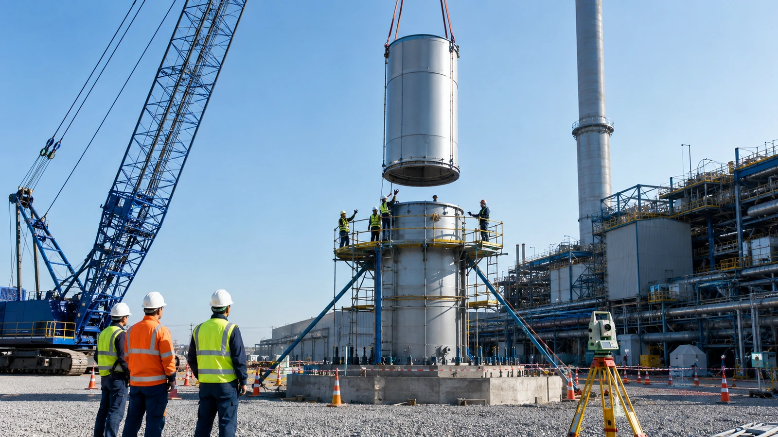
Installation starts with verification. The team checks foundation elevation, anchor-bolt position, access, crane setup and section identification.
The base section establishes the chimney axis. Surveyors check level, orientation and verticality. The installation team applies the specified leveling and grouting method, then tightens anchor nuts according to the approved procedure. Duct orientation and access-door position must be confirmed before final fixing.
Many modular steel chimneys are erected from the bottom upward. A crane lifts each section, the rigging team controls rotation, and workers connect the joint from protected positions. Field joints may be bolted, welded or use a project-specific connection. Verticality is checked as height increases so small errors do not accumulate.
Other methods can be used when site conditions require them. Rainbow’s technical page describes upright installation, inverted installation, overall lifting and a mechanical lifting/inverted approach. The selected method must match the engineered section design, temporary stability plan and available lifting equipment. See Rainbow’s overview of steel chimney installation methods.
The erection sequence must coordinate liners, insulation, guides, platforms, ladders, aviation lights, lightning conductors and monitoring ports. Some components are safer to preinstall at ground level. Others must wait until the supporting section is fixed.
Duct and expansion-joint connections should be made only after the chimney position is accepted. Forcing a misaligned duct into place can introduce loads that were not included in the design. The gas path also needs a cleanliness check before closure.
Fall protection and dropped-object control remain critical throughout erection. OSHA’s steel-erection guidance explains that changing elevated work surfaces create specific fall hazards. The project must apply the local legal requirements, approved work method and site safety plan.
Mechanical completion confirms that the chimney is installed as designed. The final survey checks verticality, orientation and key elevations. Inspectors review field welds or bolted joints, anchor bolts, grout, coatings, liner supports, expansion joints, platforms, ladders, guards, aviation lights and lightning protection.
The team should close all punch-list items before the gas path becomes difficult to access. Depending on the design, checks may include visual examination, leak testing, electrical continuity, coating repair inspection and movement verification at sliding or expansion details.
The handover package should include approved as-built drawings, final calculations where required, material and welding records, inspection reports, coating data, survey results, operating limits and maintenance instructions. Baseline photographs and inspection records make later condition assessments more useful.
Commissioning must follow the plant procedure. Controlled heat-up helps the team observe thermal movement, supports, seals and duct interfaces. Any unusual noise, vibration, leakage or restraint should be investigated before full-load operation.
Most avoidable problems begin at an interface. Buyers can reduce risk by placing clear technical boundaries in the RFQ and purchase order.
Provide complete process and site data, including upset conditions.
Name the governing code, edition and document precedence.
Define responsibility for dispersion height, foundation, duct, electrical work and installation.
Require a design basis, calculation package and drawing approval schedule.
Agree on the inspection and test plan before fabrication.
Review transport limits and erection method during engineering.
Specify the manufacturing record book and as-built handover package.
Assess the supplier’s engineering, fabrication, quality and field-support capability as one delivery chain.
Rainbow’s industrial chimney solutions cover several structural types and plant applications. For a useful proposal, the buyer should share the operating envelope, site location, required height, duct data, applicable standards and expected delivery scope.
It depends on height, diameter, material, liner system, approval cycle, factory workload, transport and site conditions. A reliable schedule should separate engineering, procurement, fabrication, delivery, civil work, erection and commissioning instead of quoting one unsupported duration.
Foundation work and factory fabrication often overlap after loads, anchor-bolt geometry and interfaces are approved. The team should not release irreversible work while key inputs remain open. Survey results must be checked before the base section is installed.
Sometimes, but only when weight, length, stiffness, crane capacity, rigging, access, wind limits and temporary stresses allow it. Many industrial chimneys use several transport and lifting sections because this lowers logistics and erection risk.
Neither is always better. Bolted joints can reduce site welding, while welded joints can provide a continuous shell. The choice depends on structural design, gas tightness, corrosion, fatigue, transport segmentation, inspection access and project standards.
Typical records include material certificates, approved drawings, welding procedures, qualification records, inspection reports, nondestructive examination results, dimensional reports, coating data, nonconformance closure and final as-built documents. The exact list should be agreed in the contract.
Install as much as practical at ground level when the engineered lifting plan allows it. This can reduce work at height, but the added weight and wind area must be included in the lift analysis. Final connections and inspections may still be required after erection.
Confirm mechanical completion, gas-path cleanliness, duct and expansion-joint alignment, anchor and joint status, coating repairs, access systems, aviation lights, lightning protection, inspection records and punch-list closure. Then follow the approved heat-up and operating procedure.

Wang Yong
Chairman
"True progress rises when industry respects the sky it touches."