What are you looking for?

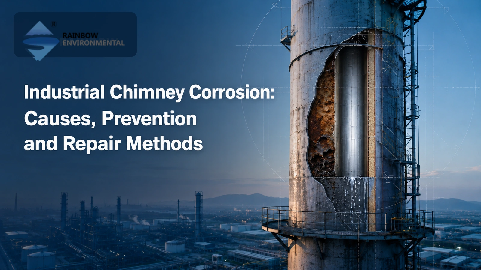
Industrial chimney corrosion usually starts when water, acidic condensate, or wet deposits remain in contact with steel, concrete, brick, or liner materials. The damage may appear as general wall loss, deep pits, cracked welds, failed coatings, loose brickwork, or leaks. The right response depends on the flue gas chemistry, temperature range, damaged component, and remaining structural capacity. For corrosive service, Rainbow can configure an industrial steel chimney with a suitable inner flue, insulation system, drainage details, and corrosion allowance instead of relying on the outer shell alone.
Corrosion is often caused by flue gas cooling, process changes, water entry, deposits, or a protection system that no longer matches operating conditions. Several mechanisms can act together, so visible rust alone does not identify the root cause.
Acid dew point corrosion is one of the main internal risks in combustion and process stacks. Flue gas may contain water vapor and sulfur, chlorine, or nitrogen compounds. When the gas or liner surface falls below the relevant dew point, corrosive liquid can condense on the wall. Sulfuric acid and hydrochloric acid are common concerns, but the actual condensate depends on fuel, process chemistry, air pollution controls, and gas temperature.
A published failure analysis of a welded 316L stainless steel stack found acid dew point corrosion followed by stress-corrosion cracking near welds. This is an important warning: using stainless steel does not remove the need to understand condensate chemistry, weld condition, temperature cycling, and local stress.
Rain can enter through a damaged cap, open joint, failed flashing, cracked concrete, or poorly sealed access opening. Process condensate may also collect at offsets, low points, expansion joints, or the base of the liner. If drains are blocked or badly placed, the liquid stays against the material and increases local attack.
External moisture can enter damaged cladding or insulation joints and remain hidden against a carbon-steel shell. The steel may look acceptable from the outside while corrosion develops below the insulation. Risk is often higher near penetrations, platforms, support rings, seams, damaged weather barriers, and areas exposed to frequent temperature cycling.
A coating can fail because of poor surface preparation, wrong dry-film thickness, chemical incompatibility, excessive temperature, thermal cycling, abrasion, or loss of adhesion. A brick, alloy, or fiber-reinforced liner can also crack, separate, leak, or fail at joints. Once the barrier is breached, corrosive liquid may attack the substrate behind it and spread beyond the visible defect.
Material selection must reflect the complete operating envelope, not only the normal gas temperature. Startup, shutdown, standby periods, low-load operation, fuel changes, scrubber operation, and cleaning cycles can create more severe conditions than steady operation.
Weld heat-affected zones, crevices, dissimilar-metal contacts, fasteners, and poorly finished seams can become local weak points. Fabrication defects can also leave areas where condensate collects.
Fly ash and process deposits may hold moisture against the surface. Some deposits contain chlorides or other hygroscopic salts that absorb water and form an aggressive electrolyte. Research on low-temperature biomass boiler corrosion shows that chlorine chemistry and moisture-absorbing salts may be more important than sulfur in some biomass systems. This means the corrosion model must match the actual fuel and process.
High gas velocity or particle loading can erode a coating or liner first. Corrosion then attacks the exposed material. This combined erosion-corrosion is common near bends, transitions, gas inlets, and flow disturbances.
Early detection reduces the chance that a local defect becomes a structural repair. Operators should look for:
rust staining, blistered paint, flaking coating, or exposed steel;
pitting, grooves, holes, or measurable wall thinning;
acidic liquid, wet ash, or deposits at the base and access doors;
cracks or leaks near welds, expansion joints, nozzles, and supports;
damaged cladding, wet insulation, or corrosion below platform brackets;
cracked liner tiles, open brick joints, bulging areas, or loose pieces;
concrete cracking, spalling, exposed reinforcement, or abnormal staining;
changes in draft, gas temperature, pressure, or condensate volume.
An inspection should connect physical damage with operating history. A visual survey is useful, but a repair decision normally needs measurements and engineering assessment.
| Inspection activity | What it can reveal | Important limitation |
|---|---|---|
| Internal and external visual inspection | Coating failure, deposits, cracks, leaks, deformation, damaged joints | Hidden corrosion may remain below insulation or behind a liner |
| Ultrasonic thickness mapping | Remaining metal thickness and wall-loss pattern | Requires a suitable grid, calibrated equipment, and accessible surfaces |
| Coating thickness and adhesion checks | Whether the protective system was applied and remains bonded as specified | Local readings may not represent the whole chimney |
| Weld examination | Surface cracks, lack of fusion, or defects linked to leakage and stress | The NDT method must match material, geometry, and suspected defect |
| Liner and joint survey | Cracked tiles, open joints, movement, chemical attack, or delamination | Some backing damage may need openings or targeted probes |
| Condensate and deposit analysis | pH, chlorides, sulfates, and other clues to the active environment | A single sample may not represent all operating modes |
ASTM E797/E797M covers manual ultrasonic pulse-echo thickness measurement and notes its use for identifying wall thinning caused by corrosion and erosion. The inspection plan should also review previous readings so the engineer can estimate corrosion rate rather than relying on one thickness value.
Access work must follow the site's confined-space, work-at-height, isolation, gas testing, and rescue requirements. Remote cameras do not replace close inspection or thickness measurement where structural damage is suspected.
Provide the chimney designer with normal, minimum, maximum, startup, shutdown, upset, and standby conditions. Include gas temperature, flow, pressure, moisture, oxygen, sulfur compounds, chlorides, particulate loading, expected condensate, and pollution-control equipment. Material selection based on nominal temperature alone is incomplete.
The structural shell and gas-contact surface do not need to be the same material. A carbon-steel outer shell can carry structural loads, while a separate alloy, coated steel, acid-resistant brick, or FRP liner handles the chemical environment. Selection depends on temperature, chemistry, movement, fire risk, and access.
A self-supporting steel chimney with a separate inner cylinder, insulation layer, and air space can separate structural and corrosion functions. It can also allow the inner flue to move under thermal expansion. The design still needs project-specific checks for condensation, supports, joints, and drainage.
Insulation can slow gas cooling and reduce condensation during normal operation. Correct sizing also matters because very low velocity and long residence time may increase heat loss. But keeping the gas above the acid dew point is not always possible, especially after wet flue gas desulfurization or during shutdown. In those cases, the liner must tolerate wet service.
Use suitable top details, weather seals, cladding laps, access-door seals, drain slopes, collection points, and corrosion-resistant drains. Make drains accessible for cleaning. Avoid pockets around stiffeners, supports, and transitions. A small geometry change can prevent liquid from remaining on a vulnerable surface.
A coating specification should define surface preparation, coating layers, stripe coating, dry-film thickness, curing limits, inspection points, and repair procedure. It must suit the temperature, thermal cycling, UV exposure, abrasion, and expected condensation.
Set baseline thickness readings after fabrication or commissioning. Repeat measurements at the same locations and add points around known high-risk areas. Inspection frequency should reflect corrosion rate, consequence of failure, access difficulty, operating changes, and previous defects. API RP 571 provides a general framework for linking damage mechanisms with suitable examination, mitigation, and monitoring methods in process equipment.
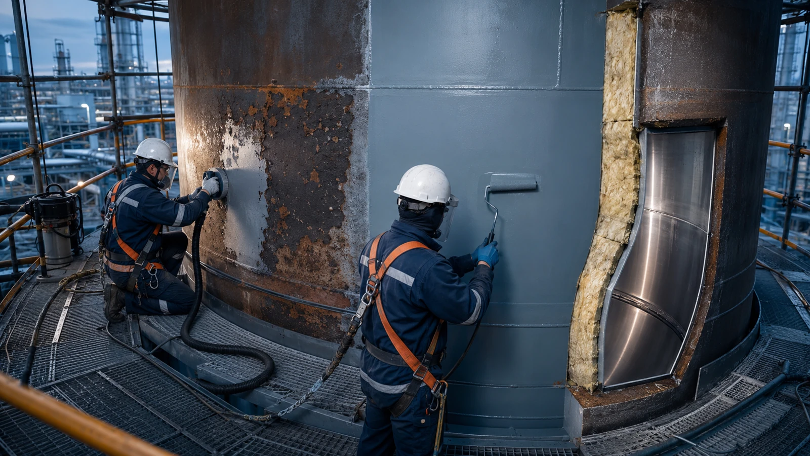
Repairs should address both the damage and its cause. Repainting a contaminated surface may only hide the problem.
Localized coating repair can be suitable when the substrate still has adequate thickness and the failed area is limited. Remove deposits and damaged coating, neutralize or wash contaminants when specified, prepare the surface, repair pits if required, and rebuild the compatible coating system. The repair boundary should extend to sound, well-bonded coating.
Insert plates, shell sections, reinforcement, or weld repairs may restore a damaged steel component. The engineer must check remaining thickness, loads, fatigue, thermal movement, weldability, and nearby coatings or liners. Cracks near stainless-steel welds need failure analysis because new welding may leave the original cause unchanged.
Joint repair, tile replacement, patch lining, membrane repair, or complete flue relining may be needed when the gas barrier has failed. A full replacement is often more reliable when defects are widespread, the liner material is chemically unsuitable, or movement has damaged many joints. Compatibility between the repair material and existing liner is essential.
Repairing the corroded metal without fixing water paths invites repeat damage. Work may need to include new drains, improved slopes, sealed penetrations, replacement insulation, repaired weather cladding, redesigned expansion joints, or isolation between dissimilar metals.
Replacement should be considered when wall loss is extensive, structural stability is uncertain, cracks are widespread, repair access is poor, or the original material cannot handle the current process. A change in fuel, scrubber, production rate, or operating temperature may make the original chimney design unsuitable even if local repairs are possible.
| Condition | Possible response | Required engineering check |
|---|---|---|
| Small coating defect with sound steel | Localized surface preparation and compatible coating repair | Contamination, adhesion, thickness, temperature, and chemical exposure |
| Local pitting or wall loss | Plate, insert, weld build-up, or component replacement | Remaining strength, fatigue, weldability, and corrosion cause |
| Failed liner joints or isolated cracks | Joint replacement or localized liner repair | Movement, backing condition, and material compatibility |
| Widespread liner failure | Complete relining or new inner flue | Temperature, chemistry, support system, expansion, and installation access |
| Wet insulation and external shell corrosion | Remove insulation, repair steel, replace insulation and weather barrier | Full extent of hidden damage and future water exclusion |
| Severe structural loss or changed process duty | Partial or full chimney replacement | Current loads, remaining life, outage plan, and lifecycle cost |
A repair specification should define measured damage, acceptance criteria, materials, welding, coating or liner work, quality checks, access, and post-repair measurements. Rainbow's 60 m waste-incineration chimney project used a Duplex 2205 inner cylinder, Q355B outer shell, and sliding supports for corrosive gas and thermal movement. It shows why material, structure, and expansion design should be considered together.
chimney type, height, diameter, wall construction, drawings, and design code;
fuel or process source and all flue gas operating cases;
pollution-control equipment and any recent process changes;
shell, liner, insulation, coating, weld, and fastener materials;
inspection reports, thickness maps, photographs, samples, and repair history;
known leaks, condensate locations, deposits, vibration, and draft problems;
required remaining life, shutdown window, access limits, acceptance criteria, and site safety rules.
This information helps suppliers compare repair, relining, and replacement on the same technical basis.
Acidic condensation is a common cause, especially when flue gas or the liner surface falls below an acid dew point. But water entry, chlorides, wet deposits, liner leakage, and unsuitable materials may also control damage. Gas and deposit analysis should support the diagnosis.
Yes. Stainless steel can pit, corrode in crevices, crack under combined stress and chemistry, or suffer attack near welds. Alloy grade alone does not guarantee performance. The design must consider condensate composition, temperature, fabrication, cleaning, and contact with other metals.
Ultrasonic thickness testing is widely used to measure remaining metal from one accessible side. A grid or corrosion-monitoring-location plan is more useful than isolated readings. Inspectors may also use visual examination, surface NDT, samples, coating tests, and liner surveys.
Often, yes, if the damage is localized and the remaining structure is adequate. Options include coating repair, steel inserts, weld repairs, liner patches, and joint replacement. Widespread wall loss, unsuitable materials, or changed operating duty may make relining or replacement safer.
There is no universal interval for every chimney. Set the interval from corrosion rate, material, operating cycle, consequence of failure, previous defects, and local rules. High-risk areas may need more frequent checks than the general shell or liner.
No. Insulation can reduce cooling and condensation during some operating cases, but it cannot guarantee dry service during shutdown, low load, cold weather, or downstream wet scrubbing. The liner and drainage system must handle the actual wet-service risk.
Failure Analysis of a Welded 316L Stainless-Steel Stack, Journal of Failure Analysis and Prevention.
ASTM E797/E797M, ultrasonic thickness measurement by manual pulse-echo contact method.
API Recommended Practice 571, damage mechanisms affecting fixed equipment.
Low-temperature corrosion in large-scale biomass boilers, npj Materials Degradation.

Wang Yong
Chairman
"True progress rises when industry respects the sky it touches."